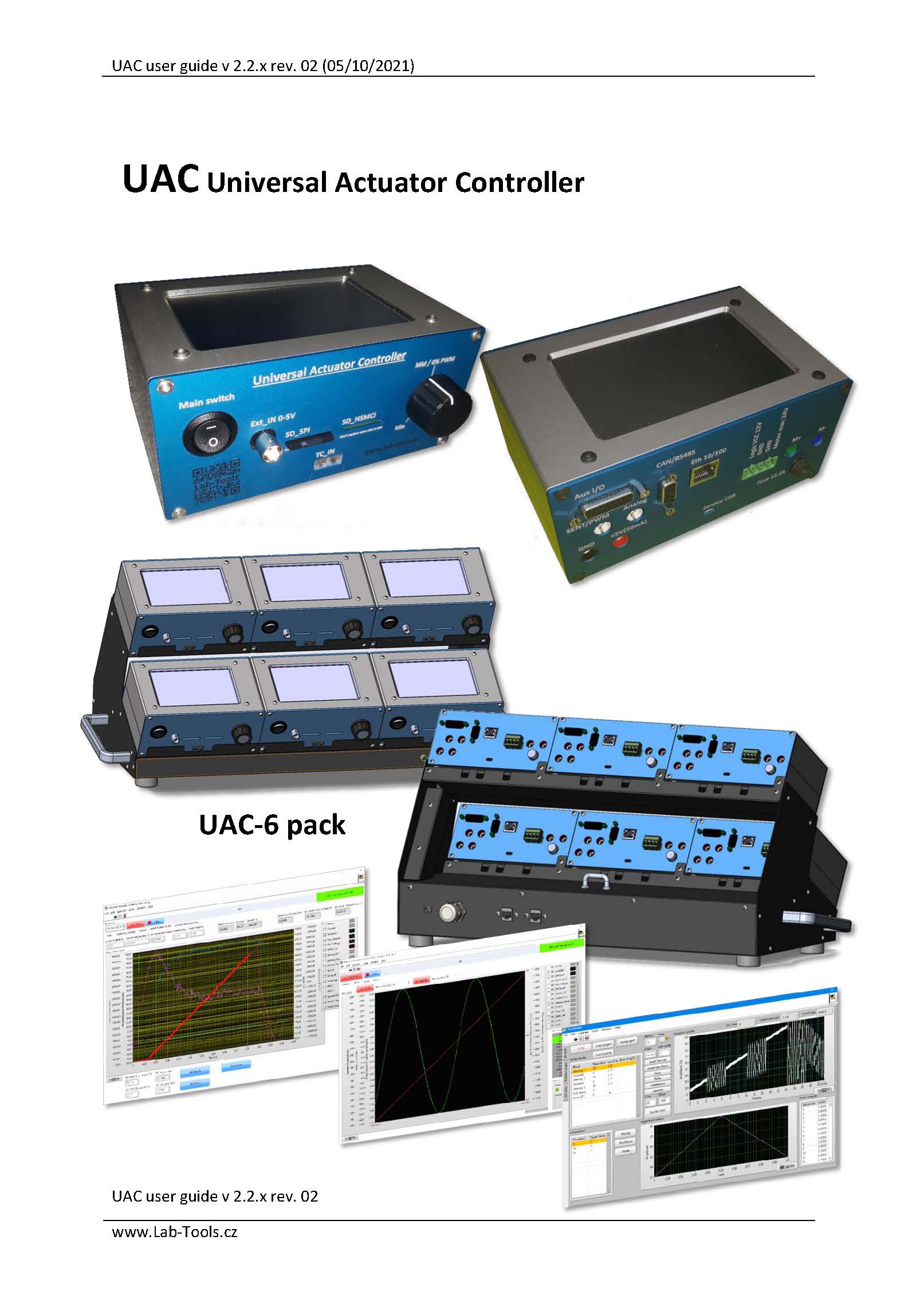
Lab-Tools The test equipement for mechatronics laboratory and more...
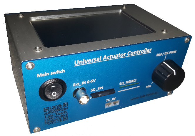
Universal Actuator Controller - UAC
UAC (Universal
Actuator Controller) is controller developed to control simple actuators with
brushed DC motor and sensor position feedback with Voltage / SENT or PWM
interface.
In future would be possible to drive also intelligent due to embedded CAN & RS485
interface (in case of interest).
Block schema of the UAC
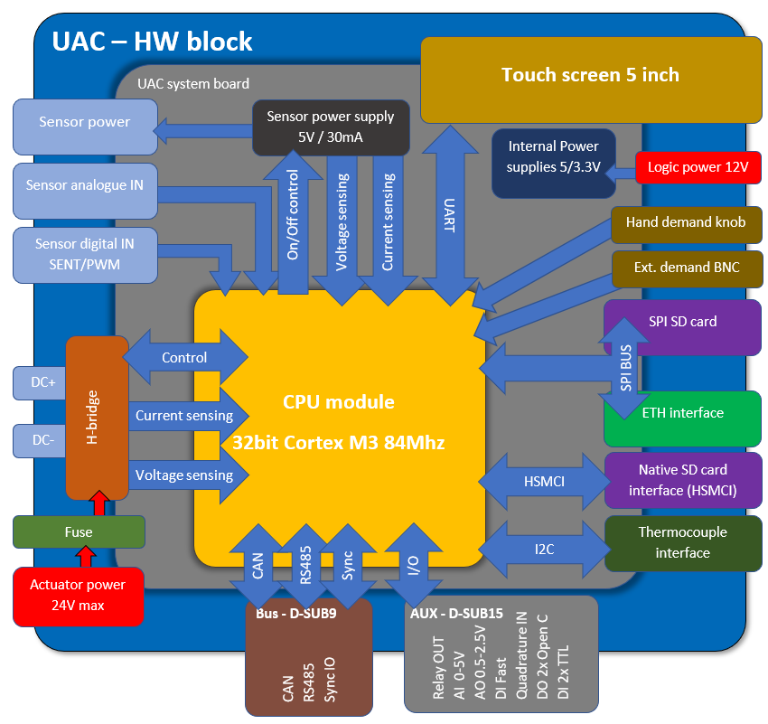
UAC system board contains main components like power supplies for all subsystems, measurement sensors and amplifiers, H-bridge, input & output conditioning circuits and protections, bus drivers and all connectors for user interfaces. CPU module is based on 32bit Cortex M3 84Mhz and is separated on dedicated board which enables simple replacement and possible upgrade to another MCU platform. Hi speed SPI bus connects Ethernet interface as main communication bus for PC interaction and also SPI mode SD card which contains all settings and calibration files of UAC. Dedicated HSMCI interface for SD card is option for future implementation of standalone recording data to SD card. I2C bus provides interface to thermocouple sensor and can be also used for future expansion with other sensors. Main user control interface is 5“ touch screen which provides all necessary user controls and indicators including live charts of control position demand and feedback as well with DC motor current.
|
Operating voltage UAC logic |
10-14V |
|
DC motor power |
7-24V |
|
DC motor current (fused) |
12.5A |
|
DC motor PWM frequency |
100Hz - 20kHz (UAC is designed for 1kHz nominal as switching time is fixed to nominal value 6.5us (error approx. 0.65% @ 1kHz). With higher frequency is timing impacted more as switching time is constant!) |
|
Signal data acquisition frequency |
All data channels 1000Hz |
|
Control loop frequency |
500Hz |
|
Sensor feedback |
Voltage / SENT / PWM |
|
Sensor power |
5V max 30mA |
|
Control modes |
Open loop + closed loop controlled by multiple inputs - see chapter Operating modes. Soft landing settings for controlled hard-stop contact - demand ramp (defining position and ramp of demand) - speed brake (imposed speed limitation) |
|
PWM limiting |
Over all limit + 3 zones according position (low, mid, high) with different setting for entering zone and exiting zone (low zone IN/OUT + high zone IN/OUT) |
|
Sensor condition test before DC motor enable |
- Voltage limit range to identify passive diagnostics - Current range to define correct current draw - SENT / PWM signal presence |
|
Memory storage |
SD card (SPI) - for PID profiles - motion profiles - UAC calibration - System settings SD card HSMCI (future implementation of standalone recording to SD card - not yet implemented) |
|
UAC communication to PC |
Ethernet 10/100 for control and data acquisition USB for service (new firmware installation) |
|
UAC communication bus interfaces |
CAN - Remote control RS485 – Future option |
|
Thermo couple interface |
Temperature measurement can be added as auxiliary channel. PID scaling according the temperature - not yet implemented |
|
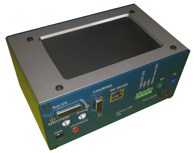
UAC IO interface |
- analog input 0-5V - analog output 0.3-3.0V - digital in (fast counter input) - Quadrature encoder interface - relay out (c, no, nc) - 2x digital in - 2x digital out (open collector max 500mA) - 5V power supply 200mA |
|
Dimension |
165x80x135mm |
CONTROLLABILITY - actuators can be controlled in open or closed loop manually by potentiometer knob, remotely by external voltage (0-5V), by CAN messages, by PC over Ethernet or by standalone motion profile uploaded to UAC. UAC can also generate sinusoidal or square movement profile defined by user.
PID TEMPERATURE SCALING (FUTUTRE OPTION) - to control actuators under various temperature profile can UAC use external thermocouple to scale PID settings to be adopted according actual temperature.
USER INTERFACE - all user control is done via 5" touch screen. Data are interpreted as text values and graphics charts. PID profiles and motion profiles must be created by dedicated SW and loaded to UAC in advance.
SD CARD SETTINGS - All settings is located on SD card and contains PID profiles according to user settings for various actuators and actuation cycle definitions.
SINE / SQUARE MOTION GENERATOR - UAC can generate sinusoidal or square movement defined in touch screen interface settings.
PWM ZONE LIMITATION - control parameters contain also PWM limitation for operating zones according to actuator position (low / mid / high zone) and also different direction of the movement. It means we can set mid position limit to 100% of PWM then low limit to 30% of PWN (in order to be sure, we don't damage actuator when we can reach hard-stop), but when exiting low zone back to mid zone we can set 100% limit again as we don't risk to hit hard-stop.
AUTOMATIC ALARMS - In every UAC PID profile are also alarm definitions which defines key characteristics of the behavior and also time window for signal averaging.
- Time duration (max 300s)
- Max average current limit
- Max average position error
- Min Pk-Pk movement
These alarms may prevent damage of tested unit or equipment and stop test in case of error.
SOFT LANDING - when approaching hardtop UAC can be set for soft landing parameters in order to limit speed of actuator. This is available in both directions where hard-stop contact may occur.
POWER - UAC uses separate power for logic of UAC and DC motor power, user can test any type of DC motor power without influence on UAC functionality.
MISS WIRING PREVENTION - To avoid miss connection of actuator cable harness is system checking sensor signal connection in order to identify correct sensor connection. Check is based on sensor feedback is in given range for passive diagnostics and current draw is also in requested range and in case of digital feedback SENT / PWM must be present before UAC apply power to H-bridge.
AUXILIARY IN/OUT - UAC can be used
with other inputs and outputs (relay OUT, Quadrature encoder, analog in/out,
digital IN/OUT and Thermo-couple measurement).
UAC user manual
UAC Software and firmware
Version 2-x-x
Note: Version 2-x-x is not compatible with 1-x-x (meaning firmware 1-x-x with Windows SW 2-x-x and vice versa). New version contains more features, so configuration files contains more parameters then used in version 1-x-x. For this reason is necessary to backup controller profiles before upgrade (ideally as screen shots) and then delete all profiles from controller. Then upgrade UAC FW, then display firmware. With new single channel utility SW 2-x-x then create all profiles again, including profile "default" which is loaded at boot of UAC!
| UAC single channel utility |
download here |
| UAC multi-channel recorder | download here |
| LabView runtime | download here |
| LabView VISA driver 15.0 or higher (needed for flashing only) | download here |
| UAC core firmware version 2-x-x | download here |
| UAC display firmware version 2-x-x | download here |
| Default display flashing bridge (in case of flashing issue) FW | download here |
Version 1-x-x
| UAC single channel utility | download here |
| UAC multi-channel recorder | download here |
| LabView runtime | download here |
| LabView VISA driver 15.0 or higher (needed for flashing only) | download here |
| UAC core firmware version 1-x-x | download here |
| UAC display firmware version 1-x-x | download here |
| Default display flashing bridge (in case of flashing issue) FW | download here |
Video 1 - UAC introduction
Video 3 - Sensor calibration test
Video 5 - Multiple UAC operation
Video 2 - Response time meassurement
Video 4 - UAC firmware upgrade
Contact: info@lab-tools.cz